GN 2241

Elastomer jaw couplings

with grub screw

GN 2241-B

Elastomer jaw couplings
without keyway

GN 2241-K

Elastomer jaw couplings
with keyway (from d1 = 30)

GN 2241-B

Elastomer jaw couplings
without keyway

Bore codes

  • Type B: without keyway
  • Type K: with keyway (from d1 = 30)

Hub

Aluminum AL

anodized, natural color
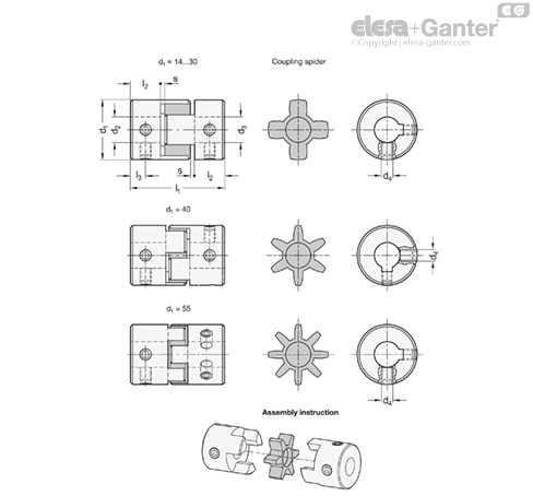
Coupling spider

Polyurethane (TPU)

temperature resistant up to 60 °C

Hardness

80 Shore A, blue BS

92 Shore A, white WS

98 Shore A, red RS

Grub screws

  • Steel, blackened
  • for d2 / d3 ≤ 4, one grub screw
  • for d2 / d3 > 4, two grub screws

Temperature range: -20 °C up to +60 °C

Elastomer jaw couplings GN 2241 can transmit very high torques while compensating for shaft misalignments and runout tolerances. They are preferred in applications where the focus lies on pure torque and power transmission.

The choice of three coupling spiders with different hardness values allows the properties of the coupling to be optimally matched to the specific requirements. The use of grub screws for clamping and the simple plug-in installation make jaw couplings very easy to assemble.

With the bore code K, the keyway is always integrated into both bores d2 and d3.

  • Coupling spiders GN 2240.1

d1Coupling spiderShore hardness coupling spiderRated torque in NmMax. torque in NmMax. speed (min-1)Moment of inertia in kgm2Static torsional stiffness in Nm/radMax. shaft misalignment
lateral in mmaxial in mmangular in Ëš
14BS80A0.71.445.0002.0 x 10-780.150.61
14WS92A1.22.445.0002.0 x 10-7140.10.61
14RS98A2445.0002.0 x 10-7220.10.61
20BS80A1.83.631.0001.1 x 10-6160.20.81
20WS92A3631.0001.1 x 10-6290.150.81
20RS98A51031.0001.1 x 10-6550.10.81
30BS80A4821.0006.2 x 10-6460.211
30WS92A7.51521.0006.2 x 10-6730.1511
30RS98A12.52521.0006.2 x 10-61300.111
40BS80A4.99.815.0003.7 x 10-53800.151.21
40WS92A102015.0003.7 x 10-55700.11.21
40RS98A173415.0003.7 x 10-512000.11.21
55BS80A173411.0001.6 x 10-414000.21.41
55WS92A357011.0001.6 x 10-416000.151.41
55RS98A6012011.0001.6 x 10-426000.11.41

If the ambient temperature is greater than 30 °C, the rated torque and the maximum torque must be adjusted using the temperature correction factors.

Ambient temperatureTemperature correction factor
-20 °C up to +30 °C1
+30 °C up to +40 °C0.8
+40 °C up to +60 °C0.7

Like all mechanical parts, shafts are subjected to manufacturing and assembly tolerances that generally cannot be entirely eliminated even with extensive technical measures. If these deviations are not taken into account in the design, the result can be vibrations, running noises, and wear or damage to the shafts and their bearings. Suitable couplings not only are able to effectively compensate for misalignment and runout errors, they also greatly simplify the assembly process, thereby reducing the overall labor required. Shaft misalignment and runout errors can vary in nature and should always be taken into consideration when selecting the appropriate coupling.

Error typeMisalignment diagram
Lateral: The axes of the shafts are in fact parallel, but they are offset laterally and do not line up.____logo__2240-BL-36192-0__
Angular: The axes of the shafts do not lie in the same plane, they meet at a certain angle.____logo__2240-BL-36663-0__
Axial: The shafts move axially along the axis of rotation.____logo__2240-BL-36669-0__
Runout: The shafts move radially out of the center of the axis of rotation.____logo__2240-BL-36671-0__

For correct fastening of the coupling hubs, the shaft must be installed according to the recommended shaft insertion depth l2. The shaft insertion depth l2 is specified in the standard sheet of the respective coupling. If the insertion depth is too low, the shaft could slip out of the coupling, or the clamping hub could break. If the shaft is inserted too far, this can cause interference within the coupling, leading to damage.


The diagrams show the change in static torsional stiffness within the permissible operating temperature range, under the assumption that the static torsional stiffness at 20 °C is 100 percent. The torsional stiffness of the couplings decreases with increasing temperature.


When the shaft ends are installed in eccentric arrangements, the coupling constantly attempts to return to its neutral position. The resulting force is referred to as restoring force. If the couplings are installed with the lowest possible eccentricity, the resulting restoring forces are lower. This also reduces the force acting on the shaft bearing.


LOOKING FOR SOMETHING:

Feeling overwhelmed with what product to choose?

Don’t delay, give OIC a call and talk to us about your industrial application. Our aim is to help your business choose the right Elesa+Ganter element for the function you need. Whether you need to clamp, close, connect, control, level, manoeuvre, measure or set. OIC has an Elesa+Ganter machine element to fit your need.

We want to find out about your industrial application need and where we can help. Our contact details are below.