EBR-SWB
Material
Glass-fibre reinforced polyamide based (PA) technopolymer, grey-black colour, matte finish.
Microswitch with button
The device is made up of a bistable normally open contact (NO).
Switching takes place by pressing the purple button, and remains switched until pressed again.
Contact resistance: max. 0.050 Ω
Isolation resistance: min. 1 GΩ at 500 VDC
Led
A red Led and a green Led can be configured through external logic to indicate the switch status.
Voltage range 24 Vdc ± 15%
Screw-covers
Technopolymer, grey-black colour, matte finish. Supplied assembled, removable by a screwdriver.
IP protection
IP 65 protection class, according to EN 60529
Standard executions
Pass-through holes for cylindrical-head screws with hexagon socket.
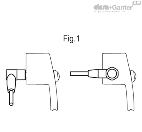
- EBR-SWB-B-C: zinc-plated connector with 8 poles, back output.
- EBR-SWB-L-C: zinc-plated steel connector with 8 poles, left side output.
- EBR-SWB-R-C: zinc-plated connector with 8 poles, right side output.
- EBR-SWB-B-F2.5: 8 pole cable, length 2.5 metres, back output.
- EBR-SWB-B-F5: 8 pole cable, length 5 metres, back output.
- EBR-SWB-L-F2.5: 8 pole cable, length 2.5 metres, left side output.
- EBR-SWB-L-F5: 8 pole cable, length 5 metres, left side output.
- EBR-SWB-R-F2.5: 8 pole cable, length 2.5 metres, right side output.
- EBR-SWB-R-F5: 8 pole cable, length 5 metres, right side output.


LOOKING FOR SOMETHING:
Feeling overwhelmed with what product to choose?
Don’t delay, give OIC a call and talk to us about your industrial application. Our aim is to help your business choose the right Elesa+Ganter element for the function you need. Whether you need to clamp, close, connect, control, level, manoeuvre, measure or set. OIC has an Elesa+Ganter machine element to fit your need.
We want to find out about your industrial application need and where we can help. Our contact details are below.